- Ć÷Ŕĺ: ľĆ´Ď´Ů
- Ľö·Î: 1
- ¸đµ¨ ąřČŁ: Jung Super
- ĂÖ´ë äłÎ´ç Ŕü·Â: Ŕüżř ľřŔ˝
- şę·Łµĺ Ŕ̸§: LUSYA
- ±Ůżř: CN (Á¤Ç°)
- Type2: Power supply board
żÉĽÇÁ¤ş¸
[(350853)Finished board]
[(193)DIY Kits]

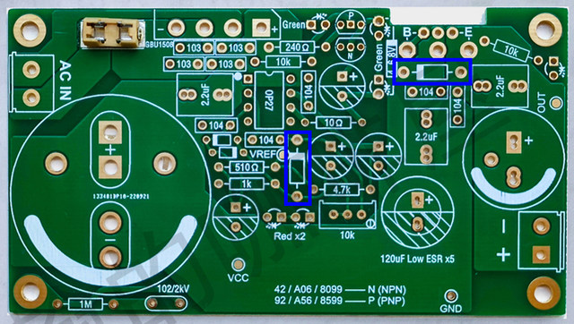
Jung Super Regulator Linear Power Board PCB

Features:
PCB board / kit information:
https://pan.baidu.com/s/1HQcu8TvIsa6tW97DYWCRiQ
Extraction code: hydw
This empty board and kit provide a list of components, and no schematics are provided! ! !
Input range: 6~33V AC or 9~45V DC
Minimum input-output voltage difference: 4V (the voltage difference is the pulsating DC voltage after rectification and filtering minus the final output voltage)
Adjustable output range: 5~28V
Rated output current of finished board: 8A
PCB design rated output current: 13.5A (in situations where a current greater than 8A is required, additional filtering capacitors may need to be added to ensure ripple current)
Load adjustment rate: up to 0.1%
The adjustment tube is compatible with TO-220, TO-3P, and TO-247, and can be externally connected using TO-3 gold sealing tubes, etc
PCB parameters:
10*5.5cm, thickness 1.6mm, white, copper thickness 1oz
Power amplifier heat sink LM1875 3886 TDA7293 pure oxidation blackening with holes
Recommended maximum dissipation power for this heat sink: 10W
Recommended maximum dissipation power for this heat sink: 10W

Welding debugging instructions:
1. It can be used after correctly welding according to the nominal component parameters of the board screen printing without any errors;
2. Pay attention to the positive and negative poles of all capacitors, diodes and LEDs (LED and electrolytic capacitor pads are square and round and negative);
3. The operational amplifier can choose low noise single operational amplifiers such as AD825 (original version), AD817, OP07, OP27 (unstable low ESR capacitive load), and OPA445 (high voltage). Please search and analyze other models yourself to determine, and the shopkeeper will not answer;
4. The 4~6.8V voltage regulator for the driving pole can also be used with 2-3 red LED series connections (4~6V), with either option.
(Even if the voltage regulator is installed, there is no need to install LED!)
5. Please use a capacitor with a withstand voltage of more than 1kV for the 102 capacitor parallel to the 1M resistor for ground discharge. The new version has been changed to 1nF (102)/2kV;
6. Please pay attention to the voltage drop of the LED used. Unless you are familiar with the circuit principle and have calculated it, do not use other colors of LEDs indiscriminately to avoid parameter deviation. All LEDs (except for output indicators) are marked with the LED colors that need to be installed near them (Red=red, Green=green/located next to the heat sink), and the output indicator LED colors can be any color;
7. When the capacitive load in the later stage is large (with a large capacitance and a large number of capacitors), it may lead to an excessive charging current of the capacitor at the moment of power on, which may burn out the fuse. At this time, it is necessary to replace the fuse from fast break to slow break, or purchase other specifications of fuses according to one`s own needs;